
News
Position:Home > News > Application
Analyze the causes of electromagnetic interference(EMI) of EV DC/DC converters, and find ways to suppress it.
——
Dilong China - Find a reliable car power supply manufacturer, order DC/DC converters and OBC, and then go to Dilong New Energy. Dilong has been focusing on the power supply industry for 20 years, from China to the world, professional / reliable / cost-effective, it is worth choosing!
——
Improving power density and conversion efficiency is an important goal of the development of EV DC/DC converters. The current mainstream technical route is to increase the switching frequency. However, power components work in high-frequency switching mode, and are prone to severe oscillation when they are turned on and off. This has become one of the main sources of electromagnetic interference (EMI) in the electrical system of electric vehicles.
The basic function of the DC/DC converter in electric vehicles is to convert the high-voltage DC power supply provided by the power battery into a voltage level suitable for the use of low-voltage electrical equipment. Different vehicles have different voltage levels, generally 12V, 24V and 48V. Although the internal topologies of DC/DC converters are different, the main part of the electromagnetic emission is similar.
When the electric vehicle is in motion, the driver responds by applying the brakes, using the light control paddles and the climate control knob. At this time, the DC/DC converter transmits low-voltage direct current to charge the low-voltage battery, and provides power for the lights, air conditioners, etc. respectively.
Due to its strong electromagnetic interference capability, it may cause risks such as failure of the electronic braking system,the electronic accelerato and the body controller.
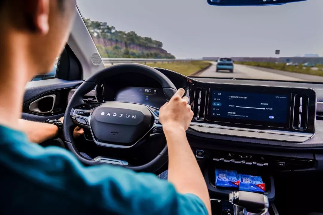
driver driving car
The parts that generate electromagnetic interference include magnetic components, power switching devices and output rectification and filter circuits. The high-frequency switching currents formed by them may generate large space radiation and cause interference.
If the capacity of the filter capacitor at the input end of the DC/DC converter is insufficient or the high-frequency characteristics are not good, the high-frequency current will cause conduction interference.
1. Power switching devices
In the DC/DC converter, the power switch tube is connected with the primary coil of the high-frequency transformer to form a switch node, and the du/dt generated at the moment of switch transition is the main source of interference.
The type of electromagnetic interference generated by the turn-on and turn-off of the power switch tube belongs to the conducted electromagnetic interference, which is formed by the transient magnetization impulse current.
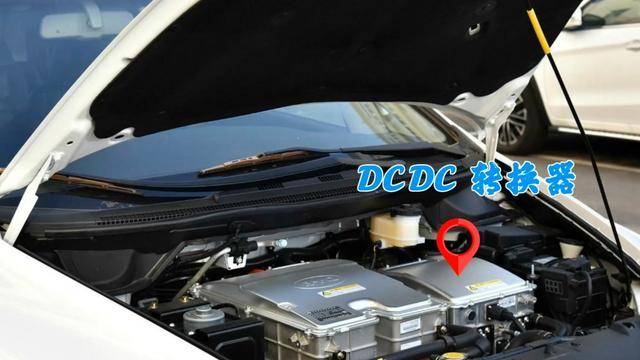
DC/DC converter installed on car
This interference will not only affect the normal operation of the DC/DC converter, but also cause more high-order harmonics.
2. Output rectifier filter circuit
The output rectifier diode will accumulate charge during forward conduction, and the accumulated charge will disappear and generate reverse current when it is turned off.
Due to the high switching frequency of the DC/DC converter, the switching process of the diode from on to off is extremely short.
Disappearing the stored charge in such a short period of time will inevitably generate a large reverse current surge, which will cause high-frequency attenuation and vibration to cause interference.
3. Methods of suppressing electromagnetic interference
3.1 Suppression of Electromagnetic Interference Produced by Power Switching Devices
The main source of interference in DC/DC converters is the high peak voltage generated at the turn-on and turn-off instants of power switching devices.
Therefore, reducing du/dt during the transition period of the power switch has become the basic idea of suppressing electromagnetic interference.
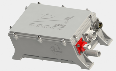
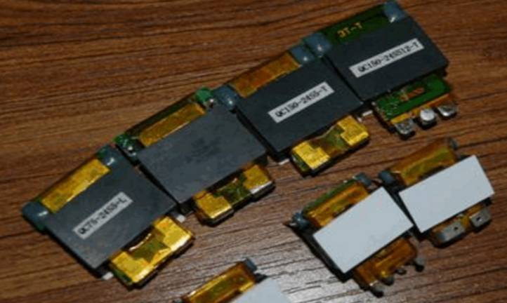
DC/DC converter (manufacturer: Dilong New Energy)
As a professional manufacturer of DC/DC converters, Dilong New Energy adopts the advanced LLC resonant switching method to suppress electromagnetic interference.
Studies have shown that Dilong New Energy's zero-voltage fixed-frequency DC/DC converter with voltage clamping has the lowest EMI level.
And can effectively reduce the parasitic oscillation caused by distributed inductance and distributed capacitance, can also reduce switching loss, improve conversion efficiency and power density.
3.2 Suppression of Electromagnetic Interference Produced by High Frequency Transformer
For the electromagnetic interference problem generated by high-frequency transformers, the core point of the suppression measures is to reduce its own parasitic parameters.
Including leakage inductance, distributed capacitance, copper loss of burning coil and iron loss of magnetic core of primary/secondary burning coil.
A planar transformer can be used to replace the traditional ordinary transformer, and its core material is made of high-power ferrite material, which has lower core loss at high frequencies.
The sintered coil is formed by stacking multiple circuit boards, and forms a transformer circuit with a flat iron core.
Planar Transformers in Switching Power Supplies
This planar transformer has low DC loss and low distributed capacitance, which can meet the requirements of resonant circuits, and the magnetic core has good magnetic shielding, which can suppress radio frequency interference.
According to the engineer of Dilong New Energy, when we produce DC/DC converters, we use planar transformers, and the company also attaches great importance to the selection of transformers.
And we have been looking for some materials that can meet higher frequencies and lower losses. At present, planar transformers are the best choice.
Compared with traditional transformers, with the same volume, planar transformers have the best heat dissipation effect and suppression of radio frequency interference.
3.3 Suppression of Electromagnetic Interference Produced by Output Rectifier Diode
The output rectifier diodes of DC/DC converters often use Schottky diodes or ultra-fast recovery diodes.
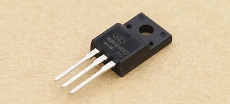
Schottky diodes
It has a very high di/dt at the moment of cut-off, except that the RC absorption loop can be connected in parallel.
It is also possible to use the equivalent inductance in the output filter capacitor to weaken the high-frequency side-pull effect of the capacitor, and to increase the structure that forms the secondary filter effect.
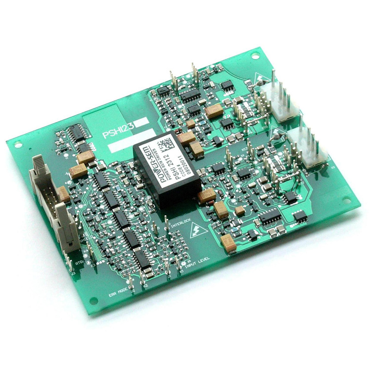
3.4 Reasonable routing and layout design of PCB circuit board
Reasonable routing of PCB circuit boards and reasonable layout design of components can also effectively reduce the electromagnetic interference of DC/DC converters.
circuit board
In terms of wiring, the distance between lines should be increased as much as possible, capacitive coupling and mutual inductance between lines should be reduced, and the loop area of interference sources and sensitive circuits should be reduced to reduce radiation interference.
And implement electrostatic shielding, and the shielding layer adopts the method of grid grounding.
In terms of layout, the components should be arranged as closely as possible, and the interrelated components should be placed together.
3.5 EMI filter
Conducted interference of DC/DC converter power lines mainly includes common mode interference and differential mode interference.
Because common mode interference and conducted interference generally exist between power lines, EMI filter design is often composed of common mode filter and differential mode filter.
Among them, the common mode filter and the differential mode filter have a strong attenuation effect on the common mode interference and the differential mode interference respectively.
When the common-mode filter is used for low-frequency noise, the common-mode inductance is mainly used for attenuation. For high-frequency noise, the common-mode capacitor, that is, the Y capacitor, is mostly used for attenuation.
Differential mode filters are generally composed of low-pass filter elements. The most commonly used is an input filter circuit formed by X capacitors directly connected in parallel between two power lines.
Selecting a capacitor with an appropriate capacity will have a strong inhibitory effect on high-frequency noise.
3.6 Frequency Jitter Technology to Suppress Electromagnetic Interference
Frequency dithering techniques use diffuse spectral energy to reduce harmonic amplitudes.
This method is for a constant switching frequency PWM control mode, and its jitter means that the switching frequency of the PWM generator changes around a certain fixed frequency while the pulse width is modulated.
In essence, under the premise of the same total energy, the energy concentrated on the harmonics is spread into a certain bandwidth near the frequency, so as to obtain a lower amplitude and reduce EMI noise.
4. DC/DCConverter electromagnetic compatibility verification
Generally, three methods are used to examine the EMI characteristics of DC/DC converters, namely radiation disturbance test, power supply terminal conduction disturbance test, and control signal line conduction disturbance test.
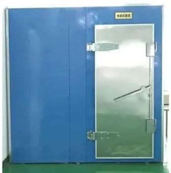
Dilong New Energy Electromagnetic Compatibility Laboratory
The radiation disturbance test is to examine the external radiation emission of the DC/DC converter from the amount of electromagnetic radiation in space.
The power terminal conduction disturbance test is to check whether it will impact the vehicle power grid by monitoring the disturbance value of the power line when the DC/DC converter is working.
5. Converter Electromagnetic Compatibility Standard
GB/T24347-2009 Electric vehicle DC/DC converter "is a national standard specially formulated for electric vehicle DC/DC converter.
The regulations on electromagnetic compatibility point out that the conducted interference and radiated interference generated by the DC/DC converter during operation should not exceed the limits specified in Chapter 12 and Chapter 14 of GB18655-2002.
6. DC/DC converter manufacturers
Dilong New Energy focuses on the research and development, production and sales of on-board DC/DC converters, on-board chargers (OBC), on-board integration and other products.
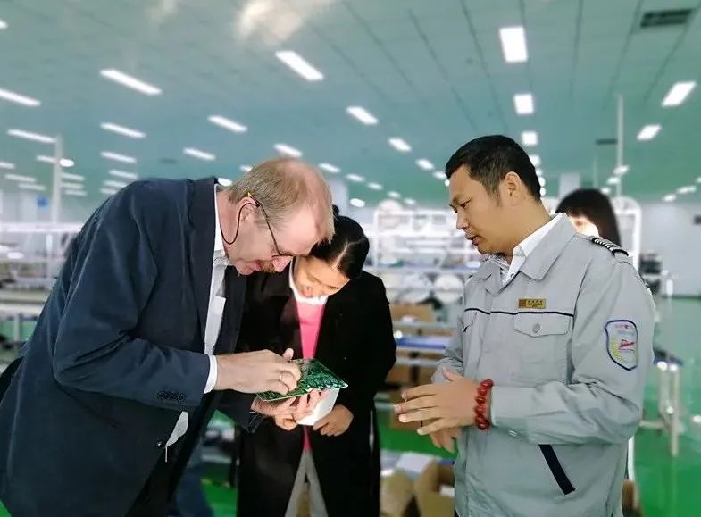
Foreign customers come to Dilong New Energy for inspection
With strong technical strength, excellent product quality and cost-effective advantages, the company has become a world-renowned supplier of automotive power supply products.
After technology research and development, the company has successfully mass-produced on-board power products, becoming one of the earliest manufacturers in the industry to integrate on-board chargers and DC/DC converters.
The company's DC/DC converters and other products have core features such as high efficiency, high power density, small size, light weight, and strong anti-interference ability, and have strong competitiveness in the international market.
We very much welcome customers to call and select DC/DC converters, and we will serve you wholeheartedly.
——
Dilong New Energy / Dilong Technology
Covering an area of more than 150 acres, focusing on power research and development for 20 years
Products include
AC/DC, DC/DC power modules
Electric vehicle power supply, vehicle power supply
OBC car charger, car DC/DC converter
Hotline: 400-666-9897
Readers and friends are welcome to reprint, share and comment
Your active participation is the driving force for our continuous creation