Position:Home > News > Application

In recent years, with the continuous development of electric vehicle charging and discharge technology, especially the continuous research and innovation of enterprises represented by dilong New energy in the vehicle charging and discharge technology, the two-way on-board charging and discharge of electric vehicles has attracted more and more attention from the market.
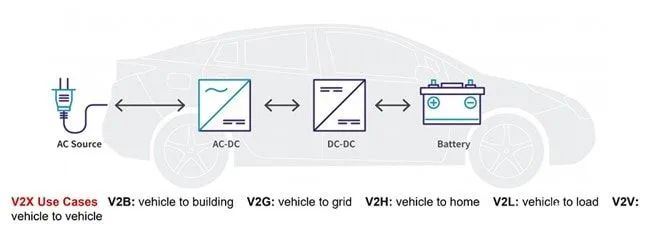
In order to meet the current new application scenarios such as vehicle power to households, vehicles for outdoor travel equipment, vehicles to power grid, and vehicles charging vehicles, on-board charger (OBC) is changing from one-way topology to two-way topology, and using two-way OBC to improve system efficiency is a new trend in the future.

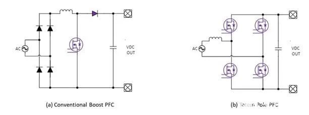
As a global high-quality OBC supplier, Dilong New Energy R & D team is developing two-way OBC products for supporting electric vehicle manufacturers. According to delillon new energy bidirectional OBC system research and development engineer: the design of electric vehicle OBC needs high power density and maximum efficiency, in order to reduce the volume and minimize the weight to achieve the purpose of saving the vehicle space. The bidirectional OBC consists of a bidirectional AC-DC converter (usually a power factor-corrected PFC circuit or active front-end AFE circuit), followed by an isolated bidirectional DC-DC converter. At the input side, the most widely used single-phase topological PFC boost converter does not support.

As shown in Figure 2, changing from boost topology (a) to totem pole PFC (b) improves efficiency and allows bidirectional operation. The totem pole PFC contains two half bridges with different power operation. The high frequency bridge arm raises and rectified and switches at high frequency; The low frequency bridge arm mainly rectified the input voltage and switches at the frequency of 50 / 60Hz.
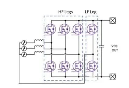
In some parts of Europe, a three-phase power supply can be used for residential electricity consumption, usually using a three-phase 6-switch PFC or AFE topology, as shown in Figure 3.

There are other types of three-phase PFC, for example, T-type PFC is a three-level converter, which has lower switching loss and smaller inductor size, but this will increase the complexity of the system, more device number, higher total cost and the overall size of the converter. Therefore, the basic 2-level three-phase PFC converter shown in Figure 3 is the most common topology of three-phase bidirectional OBC. DC-DC converters in one-way OBC usually adopt the LLC resonant topology, which is a one-way topology that limits the voltage gain of the converter in the reverse working mode, thus reducing its performance. Therefore, the bidirectional CLLC resonant converter shown in Figure 4 is more suitable for the DC-DC stage of the bidirectional OBC, which achieves high efficiency and wide output voltage range in both charge and discharge modes.

In the application of bidirectional OBC for electric vehicles, CLLC resonant converter adopts soft switch to improve the efficiency, adopts zero voltage opening (ZVS) on the primary side and secondary side ZVS + ZCS switch in the combination mode.
Another common bidirectional DC-DC converter topology is the dual active bridge (DAB), which is very simple to operate and adjusts the output through phase shifting.
However, its ZVS range is limited, and because the DAB shut-off current is higher than CLLC, the switching loss is higher than CLLC, therefore, the efficiency of DAB is lower than CLLC.